Wago Configuration
What Calaos Installer does
The Wago PLC is the backbone of most Calaos installations: it reads the switches and drives the electrical circuits.
Calaos Installer comes in at two levels:
- declaring the PLC in your project, so the server knows how to reach it;
- programming the PLC, that is, sending it the Calaos program it must run.
This page covers the software side. For choosing modules, wiring and electrical connections, see Wago PLC in the hardware chapter.
Before you start
The PLC must have a fixed IP address and be reachable on your network. This is set on the Wago side, before anything else, and is described in Calaos installation.
To check, simply open http://plc-address in a browser: the PLC’s web page must be displayed.
Write that address down: you will need it both for programming and for declaring it in the project. And give the Calaos server a fixed address too — see Network.
Programming the PLC
A PLC straight out of the box can do nothing: it needs the Calaos program.
Two routes exist, described in detail in Calaos installation:
- from Calaos Installer, which uploads the program directly;
- with Codesys, the Wago programming tool, for special cases.
The first is enough for the vast majority of installations.
The program must match the exact model of your PLC head. A program meant for another reference will not work correctly.
Declaring the devices
Once the PLC is programmed and reachable, you add your devices like any other IO: Add → Wago PLC, then the type you want — light, shutter, switch, analog input.
Each IO asks for the address of the matching input or output on the PLC. That address depends on the order of the modules on the rail: it is derived from the layout of your cabinet.
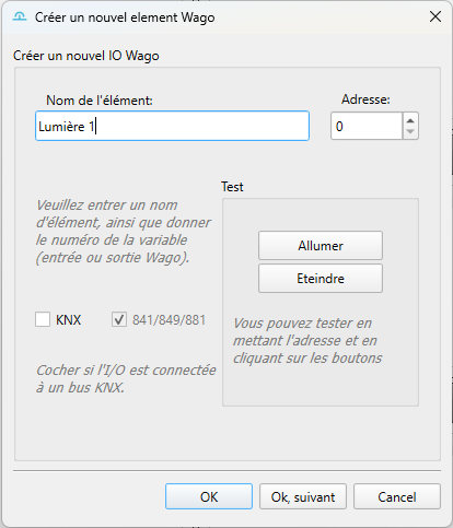
The details of addresses per module are in the hardware pages: inputs, outputs and analog inputs.
Keep a table matching each terminal of the cabinet to its device, updated as you wire. It is tedious at the time, and it is what will save you at the first fault or when adding something two years later.
Failsafe mode
The PLC embeds a standalone program that takes over if communication with the Calaos server is lost. Switches then keep driving the circuits directly, as in a traditional electrical installation.
This is an important safety net: a server failure does not leave the house without lighting. How this mode works is described in Failsafe mode.
Updating the firmware
Calaos Installer can also update the PLC firmware. This operation is rarer and more delicate than simply sending the program.
Do not cut the power or the network during a firmware update: a PLC interrupted mid-operation can become unusable.
If the PLC does not answer
Check in this order:
- does the PLC’s web page open from your computer?
- does the address declared in the project match the real one?
- are the Calaos server and the PLC on the same network?
- has the Calaos program actually been loaded onto the PLC?
If the PLC answers but the devices do not react, the mistake is more likely in the input/output addresses declared in the project than in the communication itself.
The server logs show communication errors: see Logs.