Requirements
Installation
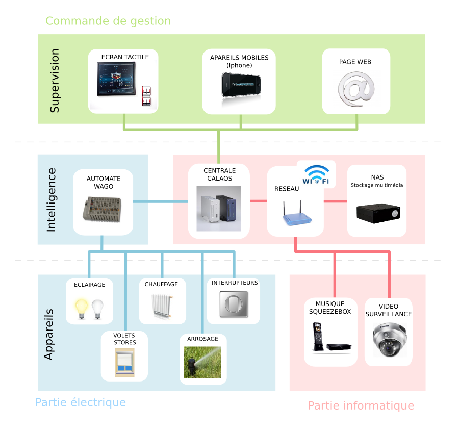
Welcome to the technical section dedicated to Calaos home automation. Here, DIY installers will find everything they need to know to complete a Calaos installation. This section includes an overview diagram of all the components in a Calaos home automation system, along with a list of the most important elements.
Through various links, you’ll have access to each product’s specifications, wiring explanations, and every programming step. Make sure to carefully read each point to not miss any installation steps.
Good luck!
Foundation
Prerequisites
For a home automation installation in a new house or as part of significant renovations, we strongly recommend starting with a Wago PLC-based Calaos approach for its durability and cost-effectiveness. Here are some key tips to get started on the right foot:
Specific Wiring Topology: The wiring architecture for Calaos with a Wago PLC is different from traditional electrical installations. It’s essential to plan for a suitable topology that will facilitate the integration of home automation and make it more efficient.
Material Compatibility: Not all electrical components are suitable for use with Calaos. Choosing compatible materials is crucial to ensure your home automation system works correctly.
While Calaos is compatible with popular technologies like Zigbee, opting for dedicated wiring and equipment from the start is the best approach for a reliable and long-lasting installation. This method minimizes the risk of malfunctions and ensures the longevity of your home automation system.
Opting for Calaos from the outset of your home design or at the beginning of a major renovation will allow you to benefit from a stable, durable, and cost-effective system in the long term.
Control Circuit Wiring
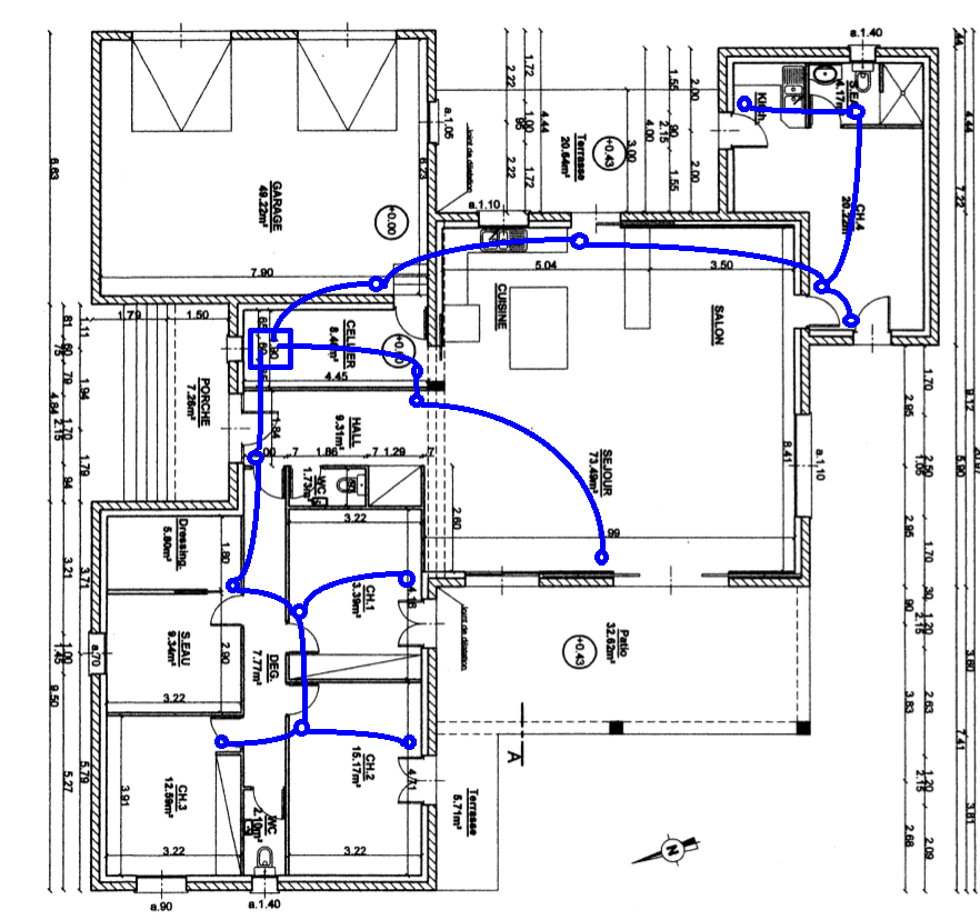
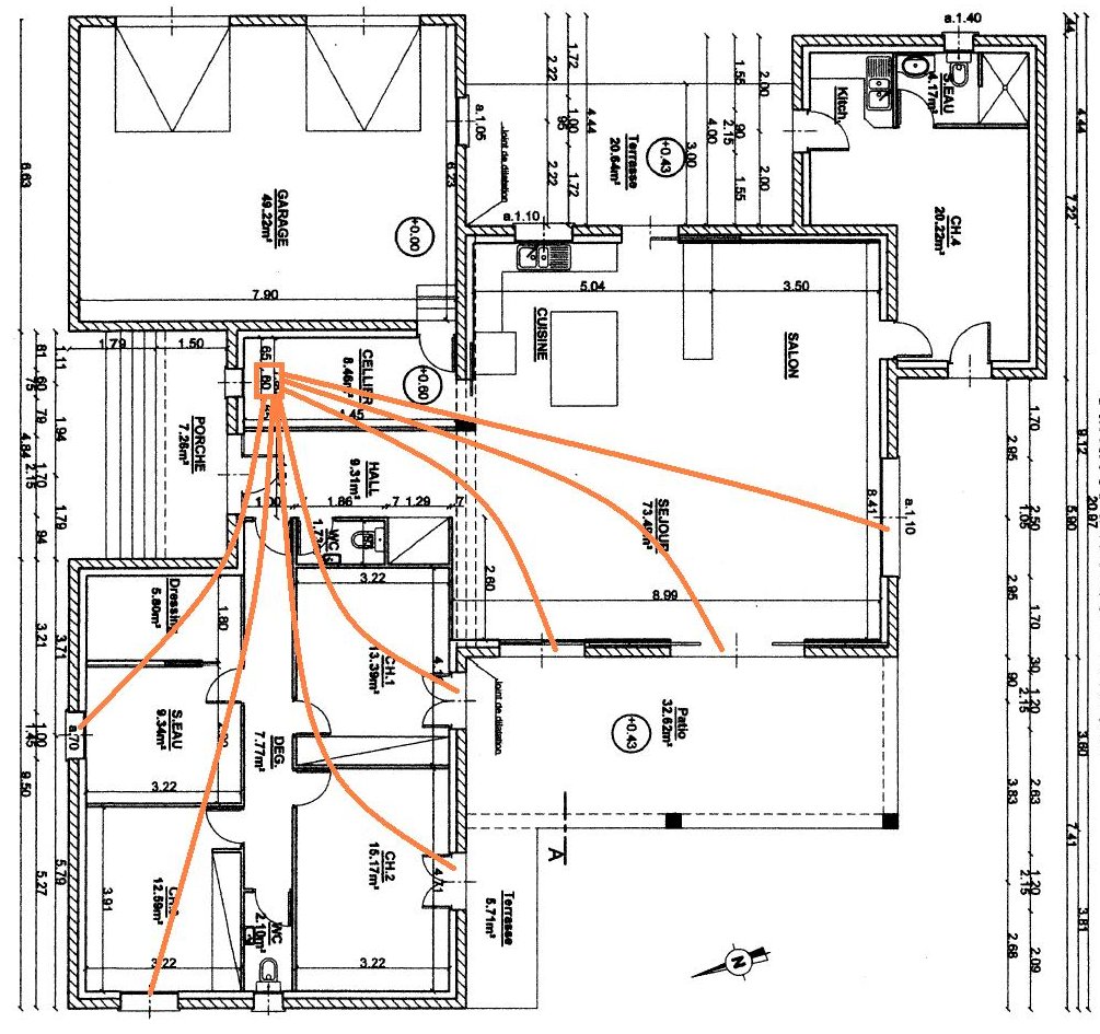
The control circuit is separate and comes directly from the communication panel or a junction box. The wiring is then done by branching loop (four or five switches in a row, depending on the type of cable) with a four-pair telephone type cable (section 0.6 mm²) or more.
All controls are simple push buttons
For example, here is a wiring diagram for push buttons. A 4-pair cable can wire up to 7 push buttons since one wire is needed for the +24v common. However, it’s sometimes better to reserve some wires for adding switches later.
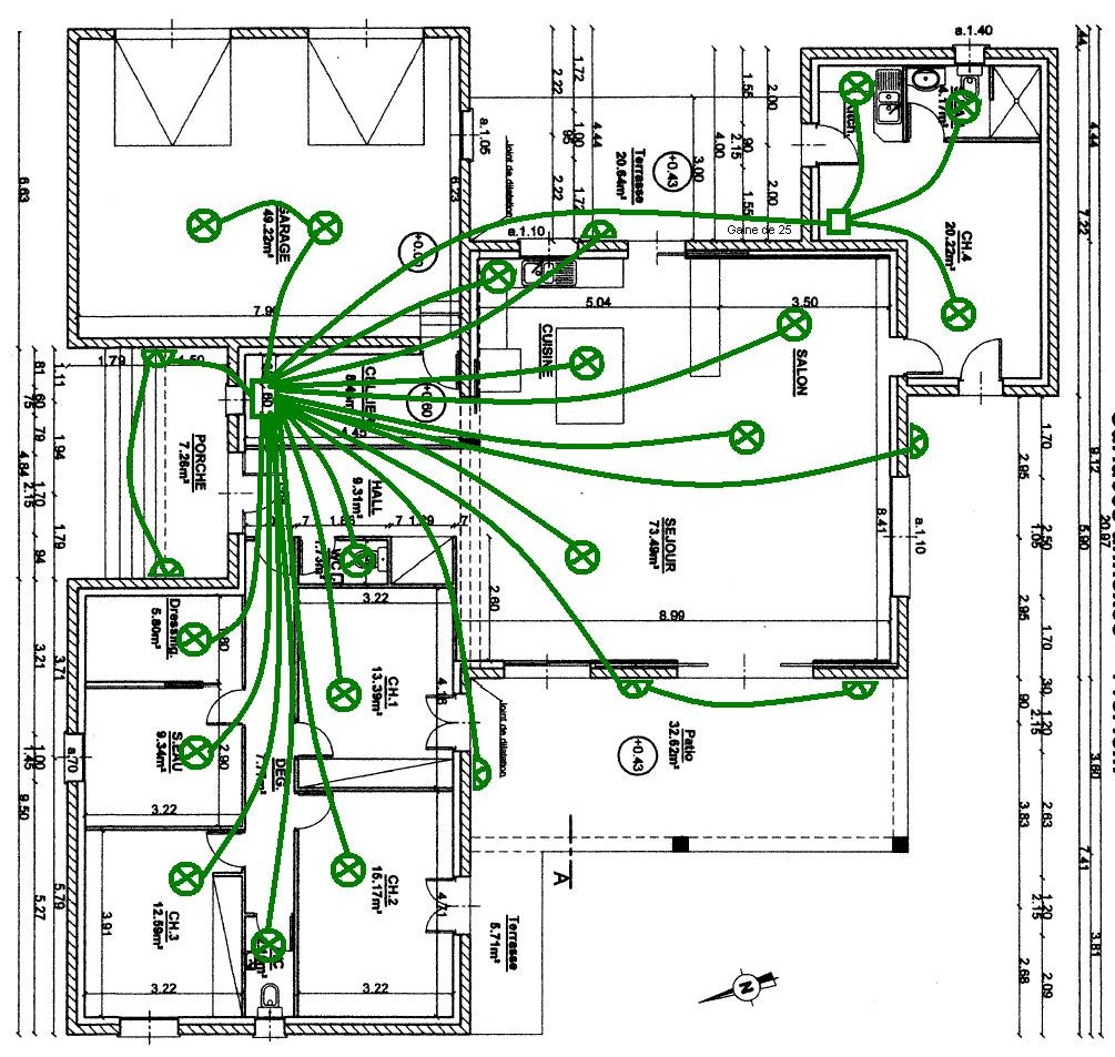
Power Circuit Wiring
The power circuit comes directly from the distribution panel or a junction box. Each circuit is separated to be controlled individually. The cable used should be of traditional section (3×1.5mm² for lights and 4×1.5mm² for roller shutters).
For compatibility with the Calaos system, all roller shutters must be wired and controlled at 230v with simple up/down actions.
For example, here is a wiring diagram for lights.
And another example with a wiring diagram for shutters.
Electrical Panel
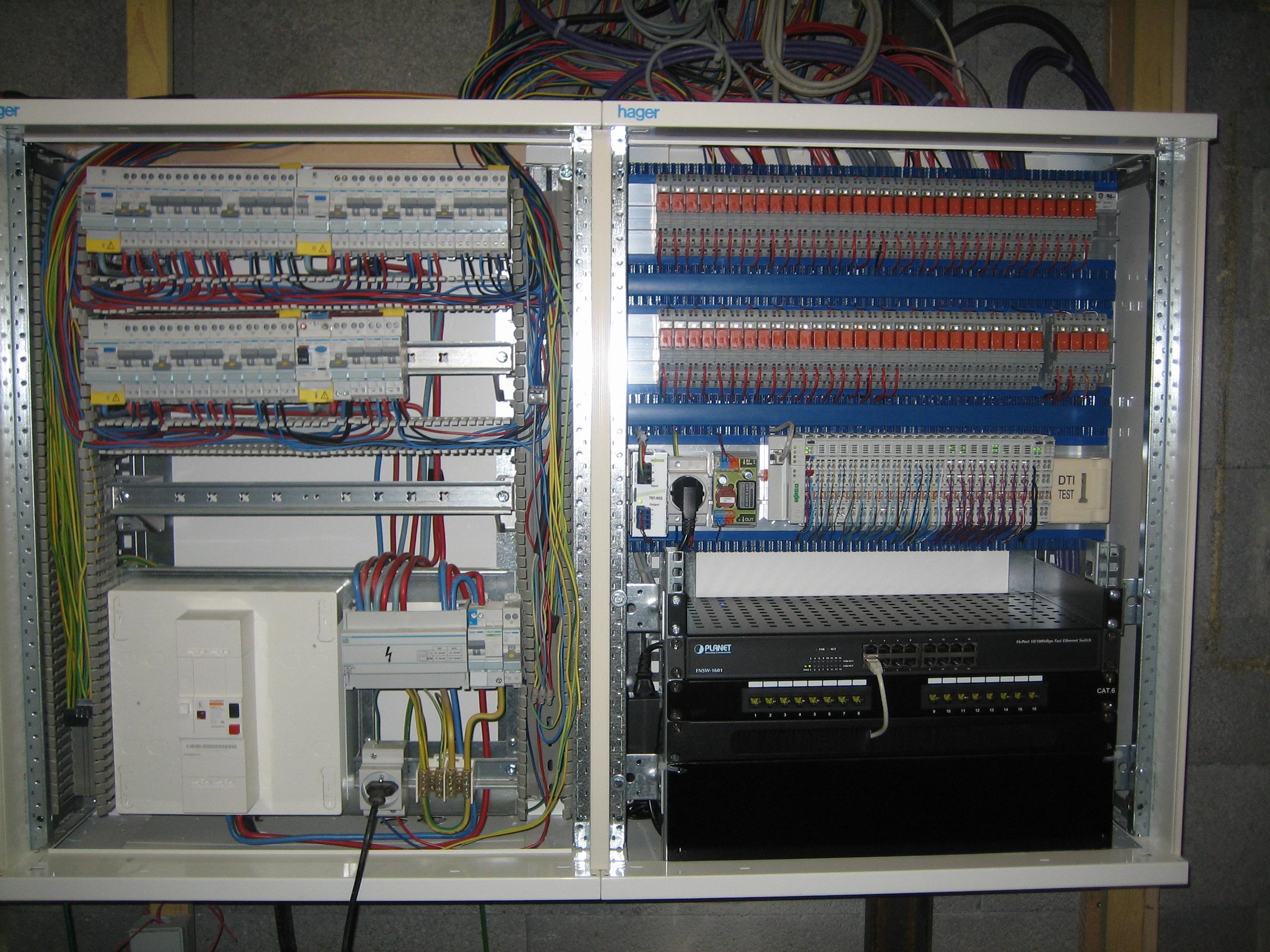
When setting up a home automation system with Calaos, especially using Wago PLCs and relays, it’s important to consider the necessary space for the installation. Due to their size and functionality, these components can take up significant space in your electrical panel.
We recommend planning for a sufficiently large distribution panel to accommodate both the traditional electrical part of your home and the additional components related to home automation. The quality and dimensions of the electrical panel are crucial for an organized and secure installation.
It’s advisable to choose an electrical panel that offers ample space for the entire system, considering not only the current dimensions of your installation but also the possibility of future expansions. Ensure that the chosen panel can accommodate the Wago PLCs and relays while leaving enough room for easy maintenance and the addition of new components if necessary.
Here’s an example of a panel, with the traditional breaker part on the left and the low-voltage part with relays, the PLC, and even the network on the right: